Sub-aperture
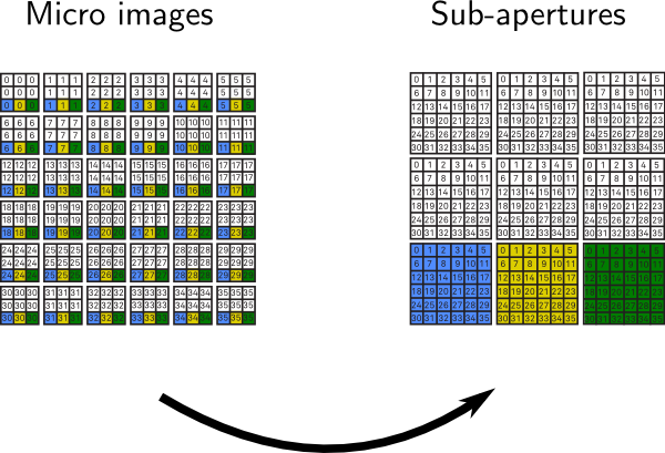
Similar to an array of cameras, the Standard Plenoptic Camera allows for a multi-view image acquisition. However, in contrast to a camera array, a plenoptic camera requires an additional image processing procedure to extract so-called sub-aperture images, which correspond to multi-view images in case of a camera array. As seen in the animation below, a sub-aperture image is composed of pixels sharing the same relative micro image position u (highlighted by colour). Further details on the triangulation, baseline and tilt angle can be found hereafter.
The sub-aperture extraction procedure collects pixels with the same distinct position u under each micro lens and places them in a new image array while each selected pixel is rearranged according to its dedicated micro lens position s. For instance, the central position u1, highlighted in yellow colour, corresponds to the central view whereas surrounding micro image positions u, e.g. blue or green, represent adjacent views from different perspective. The extraction process implies that the number of sub-aperture views amounts to the number of pixels in micro image. Consequently, the effective resolution of a sub-aperture image equals the number of micro lenses in the plenoptic camera it has been captured with. Below you can find an alternative scheme illustrating the rearrangement of pixels in the sub-aperture extraction process.
Triangulation
In stereoscopy and multi-view camera systems, it is well studied in which way the cameras' positions affect a depth map's quality. The key parameter in stereoscopic vision is the 'baseline', a technical term used to describe the distance separating optical centres of two objective lenses from each other. Although it is feasible to identify real camera positions in traditional stereoscopy, it is not obvious how plenoptic baselines and tilt angles are determined. Baseline and tilt angle parameters are needed when screening stereo or light field content on autostereoscopic displays. Besides, it would be interesting to see the impact of a plenoptic lens design on the acquired depth information. Based on the provided Standard Plenoptic Camera Model, explanations below answer these questions.
Baseline

Examination of the proposed model suggests that tracing the paths from light field rays in object space yields intersections along the entrance pupil A''. Since all chief rays, that form a sub-aperture light beam, travel through the same point A''i, this point can be regarded as the optical centre of a virtual camera lens. Accordingly, a virtual optical centre A''i is given by calculating slopes of respective object rays and finding their intersection along the entrance pupil. Similar to stereoscopic imaging, baselines BG in the Standard Plenoptic Camera can be obtained by the distance of two virtual optical centres such that BG = A''i + A''i+G .
Tilt angle
If each sub-aperture light beam belongs to a virtual camera lens A''i, its chief ray z'i can be thought to be its optical axis. An optical axes z'i may be used to indicate the tilt angle of each virtual camera lens. As depicted in the figure below, by shifting the main lens along zU, we observe that optical axes z'i change their slope with respect to zU except for the central optical axis z'0. Therefore, this behaviour can be seen as tilting the virtual camera lenses. Detailed information on the mathematical geometry can be found in this publication.

Plenoptisign - Triangulation Estimation
This section features a program to compute aforementioned light field parameters posed by any Standard Plenoptic Camera. It is its purpose to evaluate the impact of optical parameters on the depth resolution capabilities of your plenoptic camera. This may be useful (but not limited to) an early design phase, prototyping stage or calibration-free conceptualisation of a plenoptic camera that requires metric precision outputs.
Feel free to play with the default values and press "Run" to obtain your estimation results.
Demo (runs cgi_script.py)
Source Code
Related Publications
PlenoptiCam v1.0: a light-field imaging framework
C. Hahne and A. Aggoun "PlenoptiCam: a light-field imaging framework," IEEE Transactions on Image Processing, vol. 30, pp. 6757-6771 (2021).
PlenoptiSign: an optical design tool for plenoptic imaging
C. Hahne and A. Aggoun "PlenoptiSign: an optical design tool for plenoptic imaging," Software X, vol. 10 (2019).
Baseline and triangulation geometry in a standard plenoptic camera
C. Hahne, A. Aggoun, V. Velisavljevic, S. Fiebig, and M. Pesch "Baseline and triangulation geometry in a standard plenoptic camera," Int. J. Comput. Vis. (IJCV), vol. 126, pp. 21-35 (2018).
The standard plenoptic camera: applications of a geometrical light field model
C. Hahne, "The standard plenoptic camera: applications of a geometrical light field model," PhD thesis, Univ. of Bedfordshire, (January, 2016).
If you have any questions, feel free to contact me via info [ät] christopherhahne.de